
Digital to Analog Conversion Techniques:
Digital-to-analog conversion is the process of changing one of the characteristics of an analog signal based on the information in digital data.
A sine wave is defined by three characteristics: amplitude, frequency, and phase. When we change anyone of these characteristics, we create a different version of that wave. So, by changing one characteristic of a simple electric signal, we can use it to represent digital data.
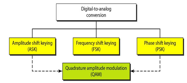
There are three mechanisms for modulating digital data into an analog signal: amplitude shift keying (ASK), frequency shift keying (FSK), and phase shift keying (PSK). In addition, there is a fourth (and better) mechanism that combines changing both the amplitude and phase, called quadrature amplitude modulation (QAM).
Bandwidth
The required bandwidth for analog transmission of digital data is proportional to the signal rate except for FSK, in which the difference between the carrier signals needs to be added.
Carrier Signal
In analog transmission, the sending device produces a high-frequency signal that acts as a base for the information signal. This base signal is called the carrier signal or carrier frequency. The receiving device is tuned to the frequency of the carrier signal that it expects from the sender. Digital information then changes the carrier signal by modifying one or more of its characteristics (amplitude, frequency, or phase). This kind of modification is called modulation (shift keying).
1. Amplitude Shift Keying:
In amplitude shift keying, the amplitude of the carrier signal is varied to create signal elements. Both frequency and phase remain constant while the amplitude changes.
Binary ASK (BASK)
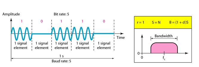
ASK is normally implemented using only two levels. This is referred to as binary amplitude shift keying or on-off keying (OOK). The peak amplitude of one signal level is 0; the other is the same as the amplitude of the carrier frequency. The following figure gives a conceptual view of binary ASKS.
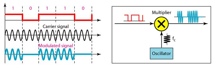
Implementation:
If digital data are presented as a unipolar NRZ digital signal with a high voltage of 1V and a low voltage of 0V, the implementation can achieved by multiplying the NRZ digital signal by the carrier signal coming from an oscillator which is represented in the following figure. When the amplitude of the NRZ signal is 1, the amplitude of the carrier frequency is held; when the amplitude of the NRZ signal is 0, the amplitude of the carrier frequency is zero.
Bandwidth for ASK:
The carrier signal is only one simple sine wave, but the process of modulation produces a non-periodic composite signal. This signal has a continuous set of frequencies. As we expect, the bandwidth is proportional to the signal rate (baud rate).
However, there is normally another factor involved, called d, which depends on the modulation and filtering process. The value of d is between 0 and 1. This means that the bandwidth can be expressed as shown, where S is the signal rate and the B is the bandwidth.
B = (1 +d) x S
The formula shows that the required bandwidth has a minimum value of S and a maximum value of 2S. The most important point here is the location of the bandwidth. The middle of the bandwidth is where fc the carrier frequency, is located. This means if we have a bandpass channel available, we can choose our fc so that the modulated signal occupies that bandwidth. This is in fact the most important advantage of digital-to- analog conversion.
2. Frequency Shift Keying
In frequency shift keying, the frequency of the carrier signal is varied to represent data. The frequency of the modulated signal is constant for the duration of one signal element, but changes for the next signal element if the data element changes. Both peak amplitude and phase remain constant for all signal elements.
Binary FSK (BFSK)
One way to think about binary FSK (or BFSK) is to consider two carrier frequencies. In the following Figure, we have selected two carrier frequencies f1 and f2. We use the first carrier if the data element is 0; we use the second if the data element is 1.

The above figure shows, the middle of one bandwidth is f1 and the middle of the other is f2. Both f1 and f2 are ∆f apart from the midpoint between the two bands. The difference between the two frequencies is 2∆f.
Implementation:
There are two implementations of BFSK: non-coherent and coherent. In non-coherent BFSK, there may be discontinuity in the phase when one signal element ends and the next begins. In coherent BFSK, the phase continues through the boundary of two signal elements. Non-coherent BFSK can be implemented by treating BFSK as two ASK modulations and using two carrier frequencies. Coherent BFSK can be implemented by using one voltage-controlled oscillator (VCO) that changes its frequency according to the input voltage.
The following figure shows the simplified idea behind the second implementation. The input to the oscillator is the unipolar NRZ signal. When the amplitude of NRZ is zero, the oscillator keeps its regular frequency; when the amplitude is positive, the frequency is increased.

Bandwidth for BFSK:
The above figure shows the bandwidth of FSK. Again the carrier signals are only simple sine waves, but the modulation creates a non-periodic composite signal with continuous frequencies. We can think of FSK as two ASK signals, each with its own carrier frequency f1 and f2. If the difference between the two frequencies is 2∆f, then the required bandwidth is
B=(l+d)XS+2∆f
3. Phase Shift Keying:
In phase shift keying, the phase of the carrier is varied to represent two or more different signal elements. Both peak amplitude and frequency remain constant as the phase changes.
Binary PSK (BPSK):
The simplest PSK is binary PSK, in which we have only two signal elements, one with a phase of 0°, and the other with a phase of 180°. The following figure gives a conceptual view of PSK. Binary PSK is as simple as binary ASK with one big advantage-it is less susceptible to noise. In ASK, the criterion for bit detection is the amplitude of the signal. But in PSK, it is the phase. Noise can change the amplitude easier than it can change the phase. In other words, PSK is less susceptible to noise than ASK. PSK is superior to FSK because we do not need two carrier signals.

Bandwidth:
The bandwidth is the same as that for binary ASK, but less than that for BFSK. No bandwidth is wasted for separating two carrier signals.
Implementation:
The implementation of BPSK is as simple as that for ASK. The reason is that the signal element with phase 180° can be seen as the complement of the signal element with phase 0°. This gives us a clue on how to implement BPSK. We use a polar NRZ signal instead of a unipolar NRZ signal, as shown in the following figure . The polar NRZ signal is multiplied by the carrier frequency. The 1 bit (positive voltage) is represented by a phase starting at 0° the 0 bit (negative voltage) is represented by a phase starting at 180°.

4. Quadrature Amplitude Modulation(QAM)
PSK is limited by the ability of the equipment to distinguish small differences in phase. This factor limits its potential bit rate. So far, we have been altering only one of the three characteristics of a sine wave at a time; but what if we alter two? Why not combine ASK and PSK? The idea of using two carriers, one in-phase and the other quadrature, with different amplitude levels for each carrier is the concept behind quadrature amplitude modulation (QAM).
The possible variations of QAM are numerous. The following figure shows some of these schemes. In the following figure Part a shows the simplest 4-QAM scheme (four different signal element types) using a unipolar NRZ signal to modulate each carrier. This is the same mechanism we used for ASK (OOK). Part b shows another 4-QAM using polar NRZ, but this is exactly the same as QPSK. Part c shows another QAM-4 in which we used a signal with two positive levels to modulate each of the two carriers. Finally, Part – d shows a 16-QAM constellation of a signal with eight levels, four positive and four negative.
.JPG "Digital-to-analog conversion_Quadrature Amplitude Modulation(QAM)")
Analog To Analog Conversion Techniques
Analog to Digital Conversion Techniques
Different Layers of OSI Model
Back to DCN Questions and Answers